Definition
- Logic circuits are fundamental components in digital electronics, used to perform logical operations on binary inputs.
- there are two types of logic circuits
- combinational circuits
- sequential circuits
Combinational circuits
- made from the basic and universal gates
- The output is defined by the logic and it is depend only on the present input states y the previous states.
Types of Logic Circuits
Adder
- circuits which performs the addition of binary bits.
- The logic circuits which performs the addition of two bit is called half adder and the three bit is called full adder
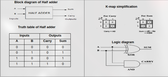
Half Adder
- the two inputs of the half adder are augend and added, the outputs are sum and carry.
Full Adder
- The three inputs of the full adder are augend, added and the carry inputs from the previous addition, the outputs are sum and carry
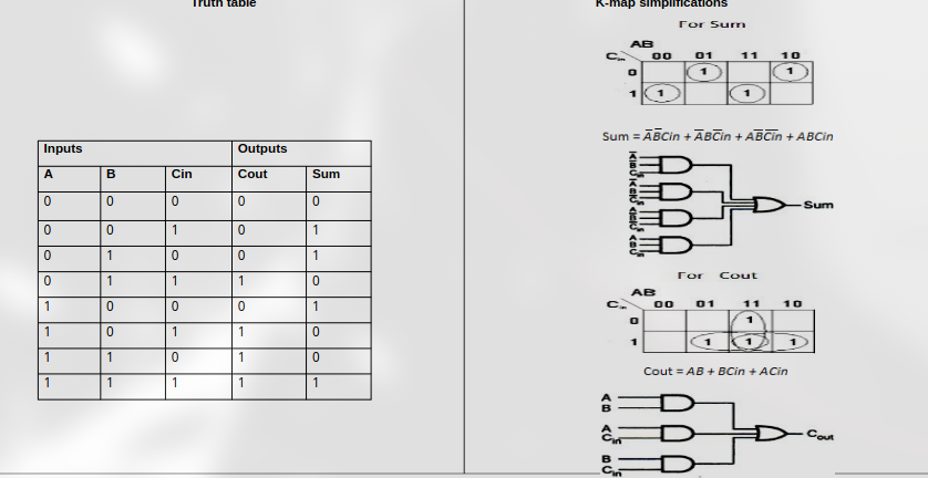
- The Full Adder can be implemented using two Half Adders and OR Gate
Subtractor
- Logic circuit which is used to subtract two binary numbers and provides difference and borrow output.
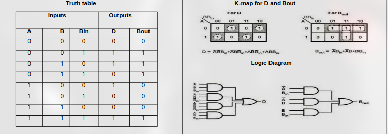
Half Subtractor
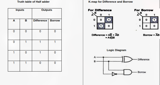
- Half Subtractor is used for subtracting one single bit binary from another bit binary
Full Subtractor
- Logic circuit used to subtract three single bit binary digits
Parallel Adder-Subtractor
1. Four bit Parallel binary Adder
- In practical situations it’s required to add two data each containing more than one bit.
- Two binary numbers each of n bits can be added by means of a full adder circuit.
2. Four Bit Parallel Binary Subtractor
- We can design four bit parallel subtractor by connecting three full subtractor and one half adder
3. Parallel Binary Adder-Subtractor
- The addition and subtraction operations can be perform using a common adder circuit, where a EX-OR gate is connected in the second input along with the mode selection bit M.
4. Carry look ahead Adder
- In parallel adder the carry input depends in the carry output if the previous stage
- This processes leads to time delay in addition. This delay is called propagation delay.
- The process can be speeding up by eliminating the inter stage carry delay called look ahead carry addition.
- In uses two functions carry generate and carry propagate
BCD Adder
- In digital system, the decimal number is represented in the form of binary coded decimal (BCD).
- The ten digit (0-9) decimal numbers are represented by the binary digits
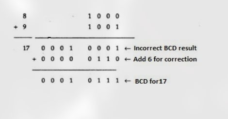
- The circuit which add the two BCD number is called BCD adder. The BCD cannot be greater than 9.
- There are three different cases in BCD Addition
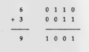
i)Sum is less than or equal to 9 with carry 0
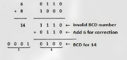
 ii)Sum is greater than 9 with carry 0
 iii)Sum equals 9 or less with carry 1